Advanced Sketching Inside Fusion 360
In the last 3D printing class you took, you studied sketching in Fusion before turning that sketch into a three-dimensional object. However, despite the fact that we did learn a good amount about the tools found in the sketching environment, we haven't looked at the full potential of the sketching tools yet. This lesson will help you get a better understanding of the geometry that you are creating while in sketch mode, as well as teach you to make precise and design-driven sketches.
Constrained vs Unconstrained Sketches
Basically, a CONSTRAINED sketch is a shape, or group of shapes, that cannot be modified in terms of their proportions and location. These are, naturally, opposite to what we would call an UNCONSTRAINED sketch, which can be manipulated in terms of proportions and location. To put it in simpler terms, as you know from the previous class, you can drag around shapes that you have sketched by clicking and dragging either a side or a point in your shape. You are able to do this when your sketch has blue edges and blue points. However on a CONSTRAINED sketch, which would have black edges and black points, you will notice that you are unable to click and drag the shape around. Therefore, this indicates that our sketch is CONSTRAINED.
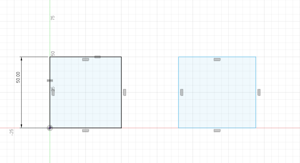
A CONSTRAINED sketch, like the one on the left, has black edges and points while an UNCONSTRAINED sketch, like the one on the right, has blue edges and points. Do you have any ideas as to why the left rectangle is constrained and the right rectangle isn't? Hint: look at some of the additional markings around the left rectangle that the right rectangle doesn't have, and also think about the left rectangle's location relative to the origin point.
Different Types of Constraints
Now, let's talk about the various types of constraints found in the sketching environment, and learn what they mean.
The Sketch Dimensions Constraint
![]()
You might remember this tool from the last 3D printing class that you took. Basically, this constraint can assign a real-life measurement to a particular side of your sketch using real-life units of length (in millimeters, inches, centimeters, feet, meters, etc) but as it turns out, it can also be used to assign a specific angle between two lines. You can assign a length to any line segment, or any segment really, by either clicking it directly (only able to do this if you're working with a line; if you click the edge of a circle or arch you will give the circle's diameter a length, and in the case of the arc, give the arc's radius a length), or you can also click two different sketch features to define a given distance as long as these features in question are either lines or points.