Lesson 6: DriveBase
1. Attention (5 Min.)
Drive trains are the most important mechanism on your robt, as they provide a foundation for your robot and allow it to move around the field to score points. There are a number of different types of drives that each have their pros and cons when it comes to a given competition. The following video explains them well:
2. Learners Guidance
The Tank Drive
The tank drive is just a Drive that has a motor on the left side and a motor on the right side. If both motors turn at equal speeds the drive goes straight. If the Left side goes faster than the right, the drive will turn towards the right. To turn left the right motor turns faster than the left motor.
Each side can have one motor or several motors. On each side all motors turn at the same speed.
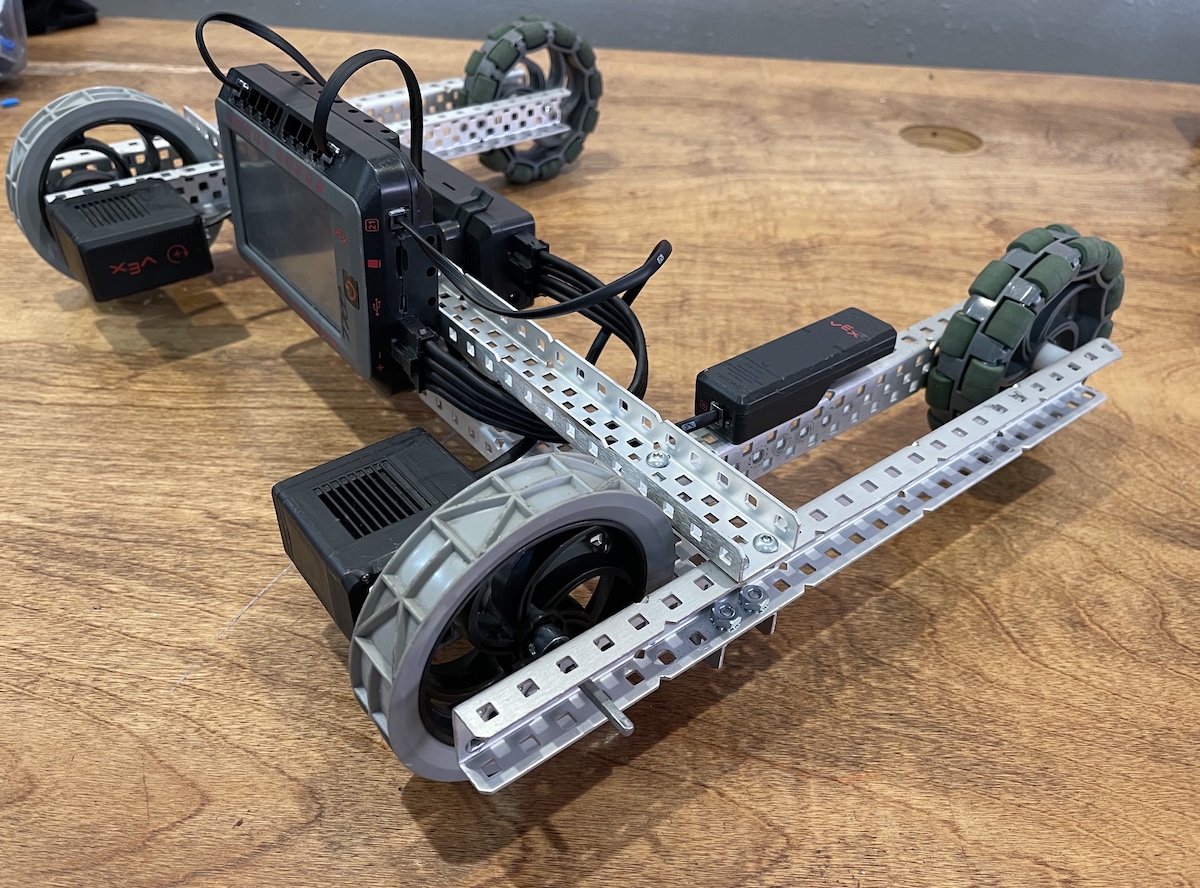
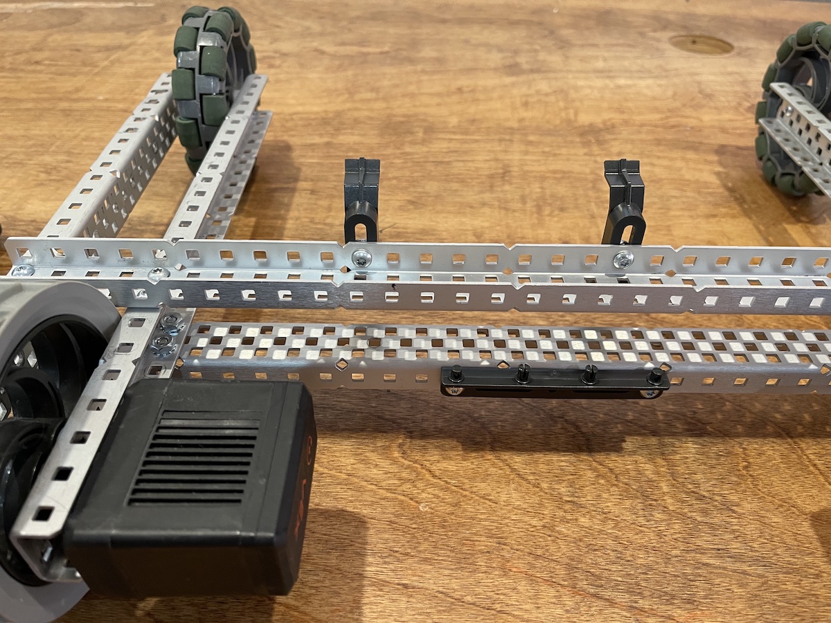
Here is the drive base that we will be building. it is a 2 motor tank drive , one motor on each side. The motors directly drive a single traction wheel. The second set of wheels are omnidirectional wheels that allow the wheels to roll sideways, this make the drive very easy to make fast turns. It also makes it a little hard to learn to drive well.
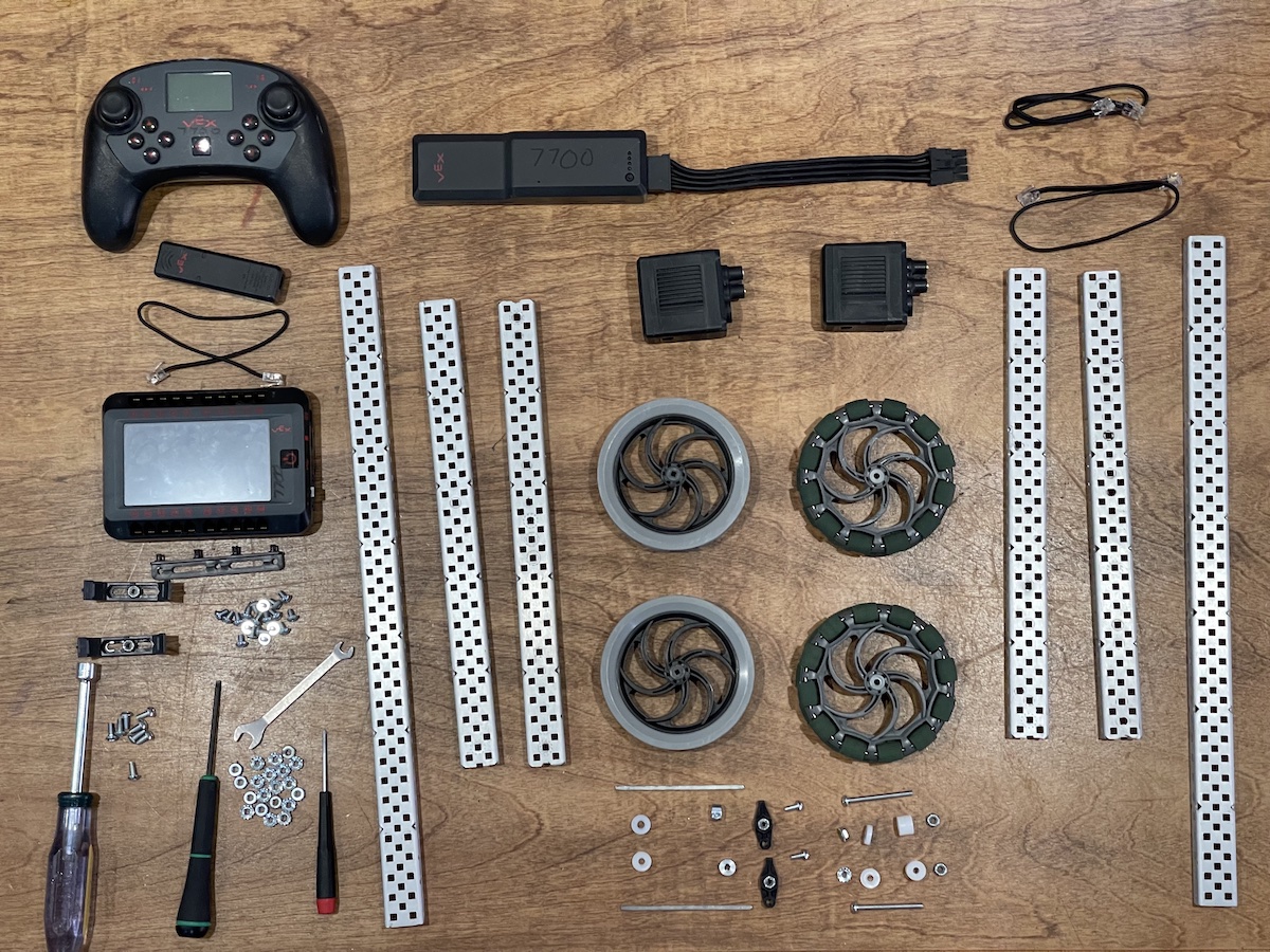
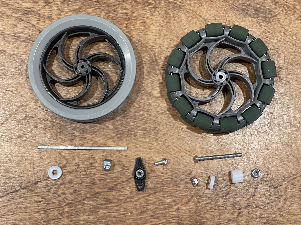
These are the parts we will need to build this tank drive. It is Ok to substitute parts if checked by instructor. For example sometimes we build the drive base to be shorter or longer and could be anything from 25 wide to 35 wide.
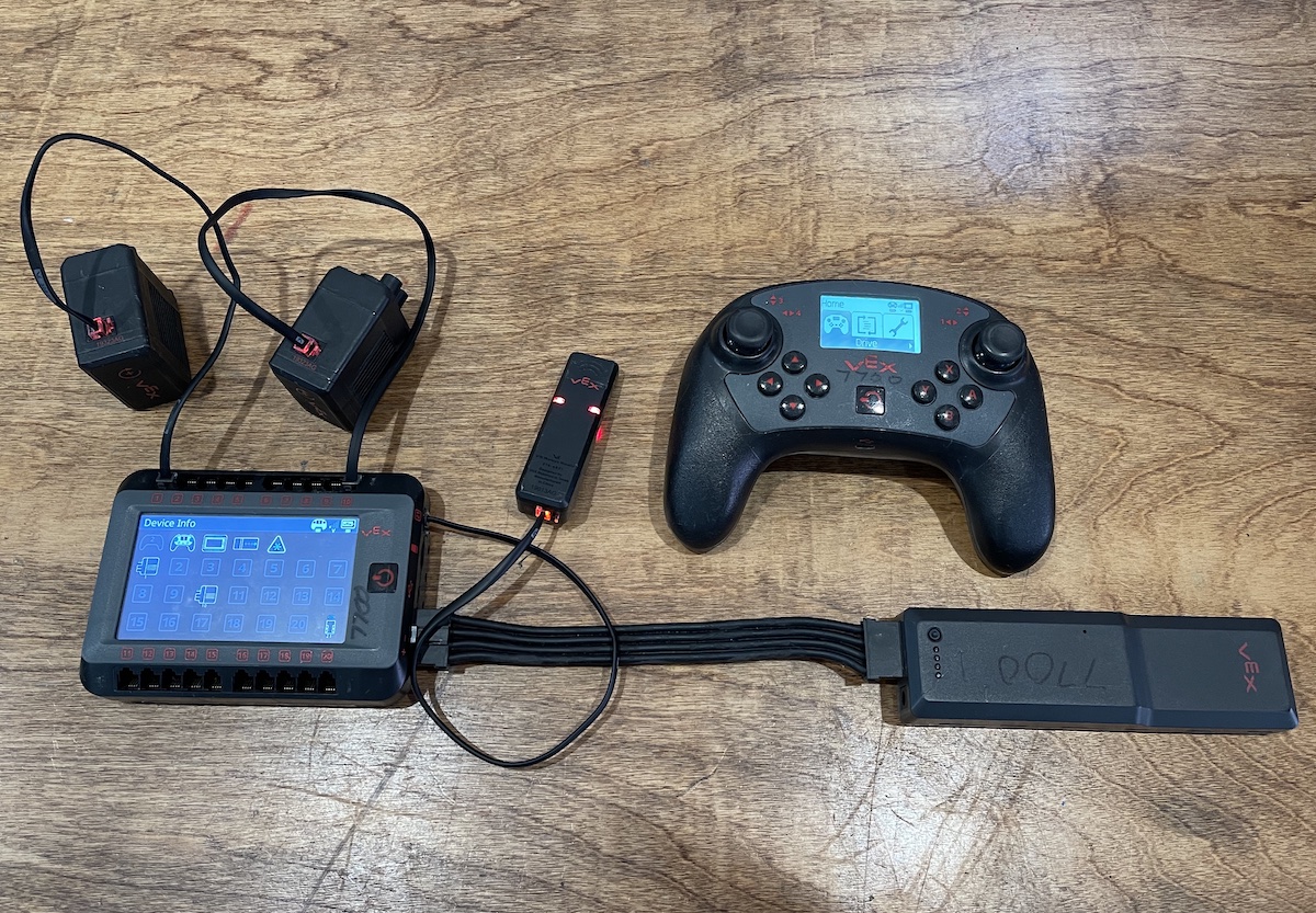
Before we build it is a good idea to test the electronics. We would not want to spend a lot of time building and only later find a faulty motor or wire. Whenever you add a motor or sensor to your robot you should test it first.
Our test is to just plug everything in and check the devices menu. All devices should show on the screen and show a solid red light at their connector.
When the radio and remote are connected there should be red lights blinking on the radio.
The included drive code can be run to test that the remote can control the motors.
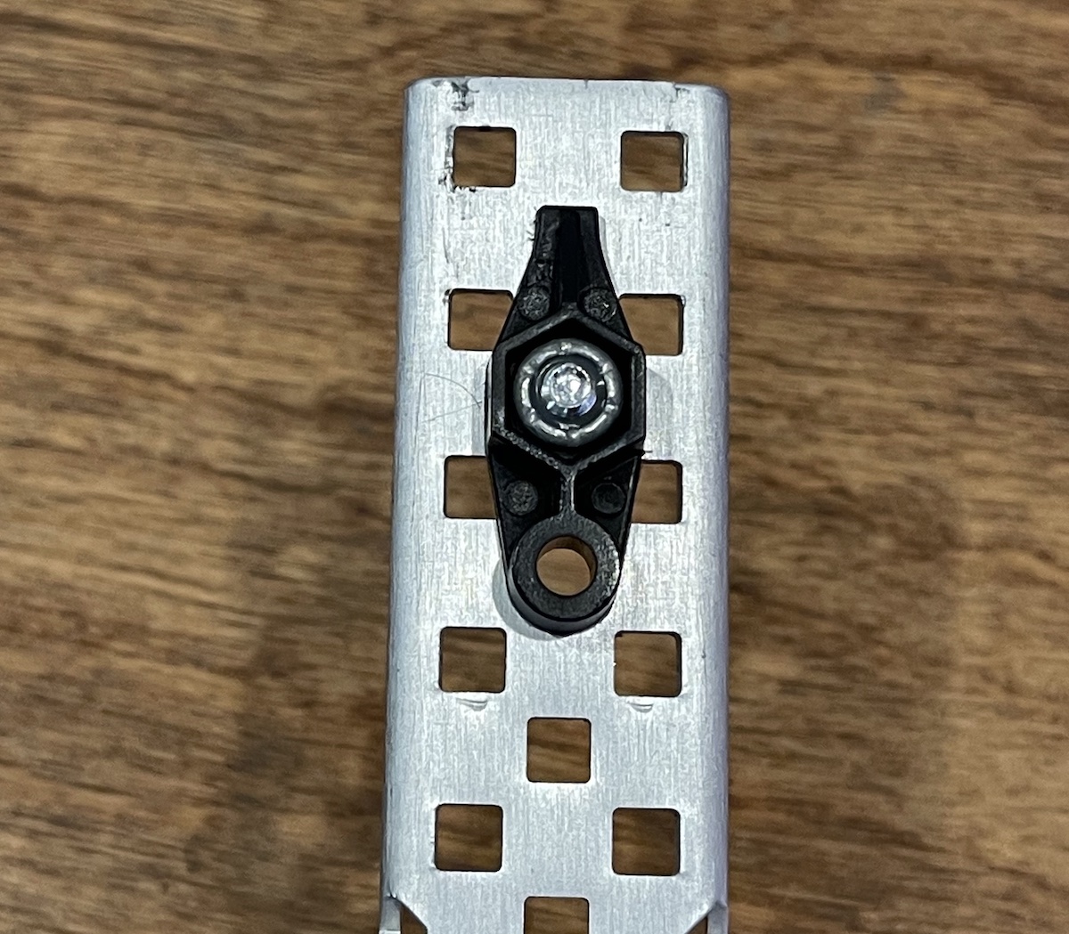
On one end we have a single screw bearing. The axle goes through the round plastic hole at the third hole of the c-channel.
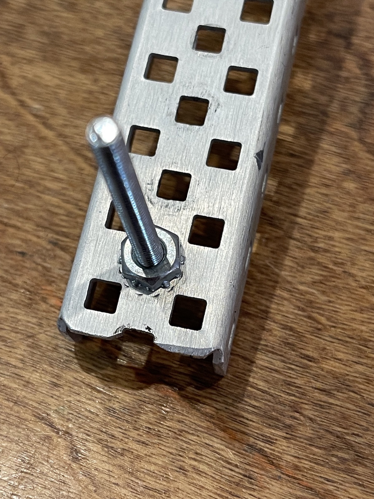
On the other end is a screw that is configured to be a dead axle. it is said to be dead since it does not turn, rather the wheel spins freely on it.
The wheels are mounted with the correct amount of spacer to make it fit between the 2 chassis rails, but not too tight, that would make for high friction.
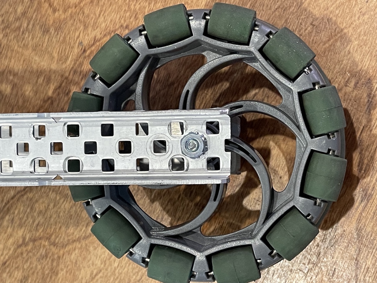
For the omni wheel it will be better to use 2 of the same size spacers. So 2 units on each side.
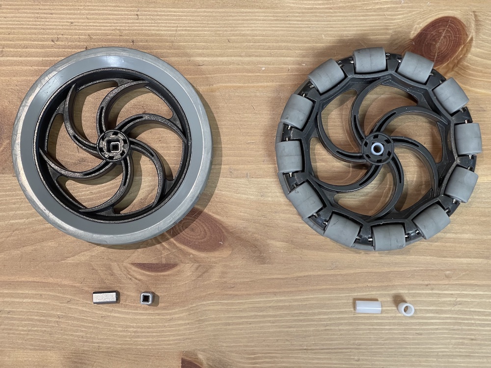
There are new wheel inserts, so if the usual are not available here is how the new ones work.
For the driven wheel that connects to the motor use the metal square insert that is 1/2" long. See the traction wheel on the left.
For the free spinning wheel use a white spacer that fits into the square hole, it is 1/2" long. See the Omni wheel on the right.
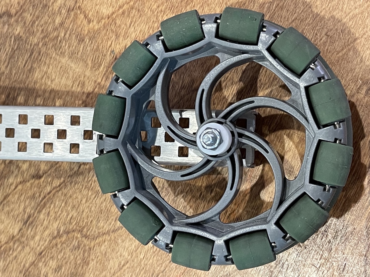
On the dead axle the wheel and spacers are stacked then finished with a nylok nut to hold the wheel tight but allow it to spin freely. A technique for this is to tighten until the wheel can not spin then loosen up just enough to allow the wheel to spin freely.
After placing the second chassis rail on the dead axle we tighten down a star keps nut. This make the dead axle part of the drive base structure, as the 3rd point defining the plane of the chassis rails.
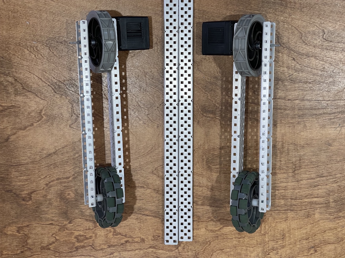
Now we have two identical sides that we will connect by cross structures
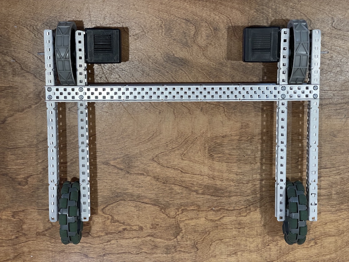
A c-channel top and bottom complete the structure. Here we use full length c-channels making the drive 17.5 inches wide. The drive can be made with shorter c-channels as well.
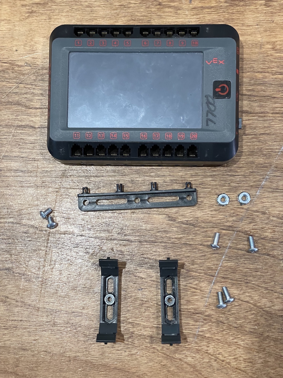
Time to mount the brain and battery clips. Here are the parts needed.
Clips mount like this.
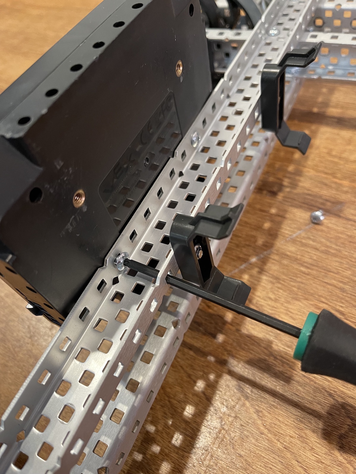
The brain mounts with 2 screws. it is important to not use screws more than 1/4 inch long. Here also is shown a build technique where the tool goes through on hole on the C-channel to turn the screws on the other side.
With the brain mounted all that remains is to wire it up.
Wiring up the Robot
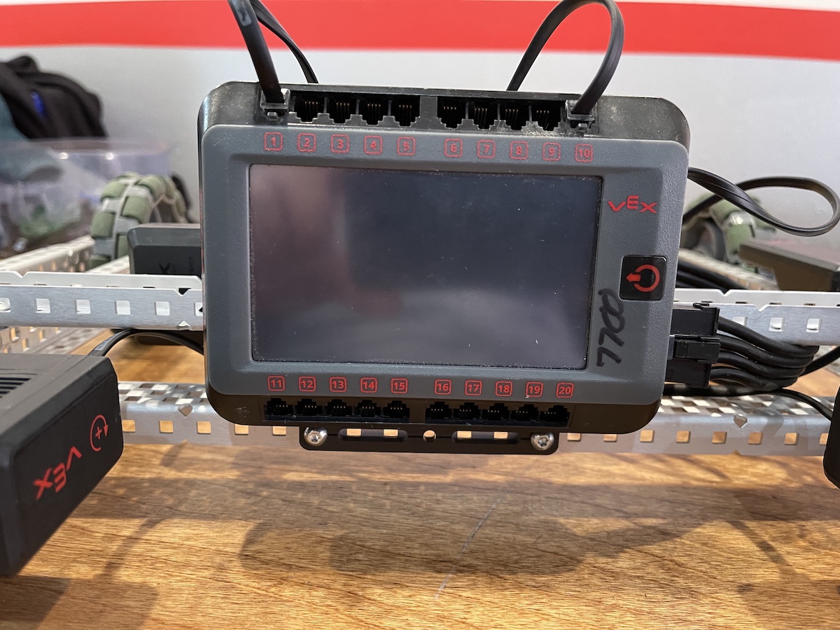
We will be using the included drive code for the first tests so there is a specific way to wire the motors. We will use port 1 for the left side motor and port 10 for the right side motor. The radio will be plugged into port 21 on the side of the brain. The battery is plugged in with a 4 wire power cable to the side of the brain.
3. Explore (25 - 30 Min.)
Have the student try to build a 3 Dimentional structure using c-channels without using any triangles. After about 10 minutes, take turns putting force on the structures to show how easy they bend or warp. Then, add more c- channels to form triangles. Once everyone is done, show how the structures are much more stable with the triangles than without.
4. Closure (5 Min.)
Have the students reflect on the importance of good building principles and discuss how they plan to incorporate them into their robot.