Digital Electronics
Digital and Analog I/O with Arduino
In this section we will use the Arduino to make measurements of continuity and voltage.
Concepts covered:
- variable types
- digital Write / Read
- analogRead
- integer and decimal math
- Serial Output
Arduino Programming
When you open the IDE you get a blank program that has the basic parts of an Arduino project.
void setup() {
  // put your setup code here, to run once:

}

void loop() {
  // put your main code here, to run repeatedly:

}
Each Arduino Program must have a setup and a loop. The setup runs once to prepare things, the loop repeats over and over. We may also put code before setup to define variables or custom functions and other things.
Serial output
We will be using Serial Output to print information to the screen. To do this we must first start a serial connection with:
Serial.begin(9600);
This code starts a connection at a rate of 9600 bits per sec. Other data rates are available we just have to make sure that the send rate is the same as the receive rate.
Once this is set we can output data using
Serial.println("Hello World ");
this will print Hello World to the screen or anything else you write between the quotes. println prints then moves to the next line. print will print everything on the same line, you should try both.
complete code to print Hello World to the screen is here:
void setup() {
  // put your setup code here, to run once:
Serial.begin(9600);
}

void loop() {
  // put your main code here, to run repeatedly:
Serial.println("Hello World");
}
Upload to Arduino Board
The code you have written is on the laptop you now need to transfer it to the Arduino board.
- Connect USB cable from laptop to Arduino board
- Select the board type Tools/Board/Arduino Uno
- Select the port Tools/Port/dev/usbmodem....
- Click the Upload arrow
If there are no errors you should get a message upload completed and the code will run.
Important:
Every time you make a change you must again upload to the Arduino board by clicking the upload arrow.
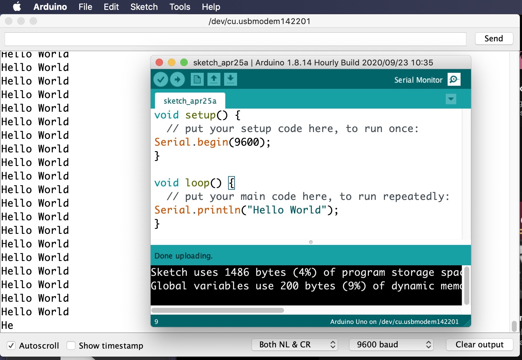
The Serial Monitor is opened by clicking the magnifying glass icon in the top right corner of the Arduino IDE window. The data rate or baud rate is set at the bottom right of the monitor window. if it is not correct you will get digital gibberish
Digital I/O
Each of the Arduino pins can be used as digital input or output. Digital means it can have one of two values, 1 or 0, true or false, HIGH or LOW. We can create a variable to hold a digital value. This is a variable of type boolean or bool.
bool circ=0;
This has created a boolean variable named circ and set it to equal 0 or false.
pinMode(2, OUTPUT);
pinMode(3, INPUT);
pinMode(4, INPUT_PULLUP);
Sets pin 2 to be and OUTPUT, pin 3 as INPUT, and pin 4 as an INPUT that starts at HIGH when not connected to anything.
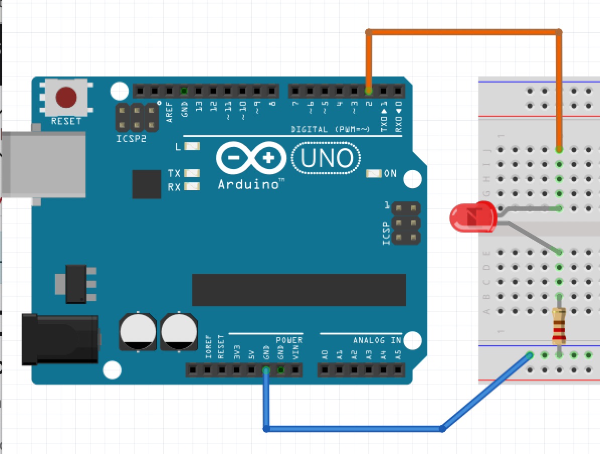
Breadboard circuit with one LED. the resistor is 220 ohm or higher to protect the LED. Be sure you have a complete circuit
We will write simple code to blink the light using
digitalWrite(2,HIGH);
delay(500);
digitalWrite(2,LOW);
delay(500);
We will put this code in setup as an indicator that we have setup the arduino. When setup is done we will blink the light twice and then leave it on.
void setup() {
  // put your setup code here, to run once:
Serial.begin(9600);
pinMode(2,OUTPUT);
digitalWrite(2,HIGH);
delay(500);
digitalWrite(2,LOW);
delay(500);
digitalWrite(2,HIGH);
delay(500);
digitalWrite(2,LOW);
delay(500);
digitalWrite(2,HIGH);
delay(500);
}

void loop() {
  // put your main code here, to run repeatedly:
Serial.println("Hello World");
}
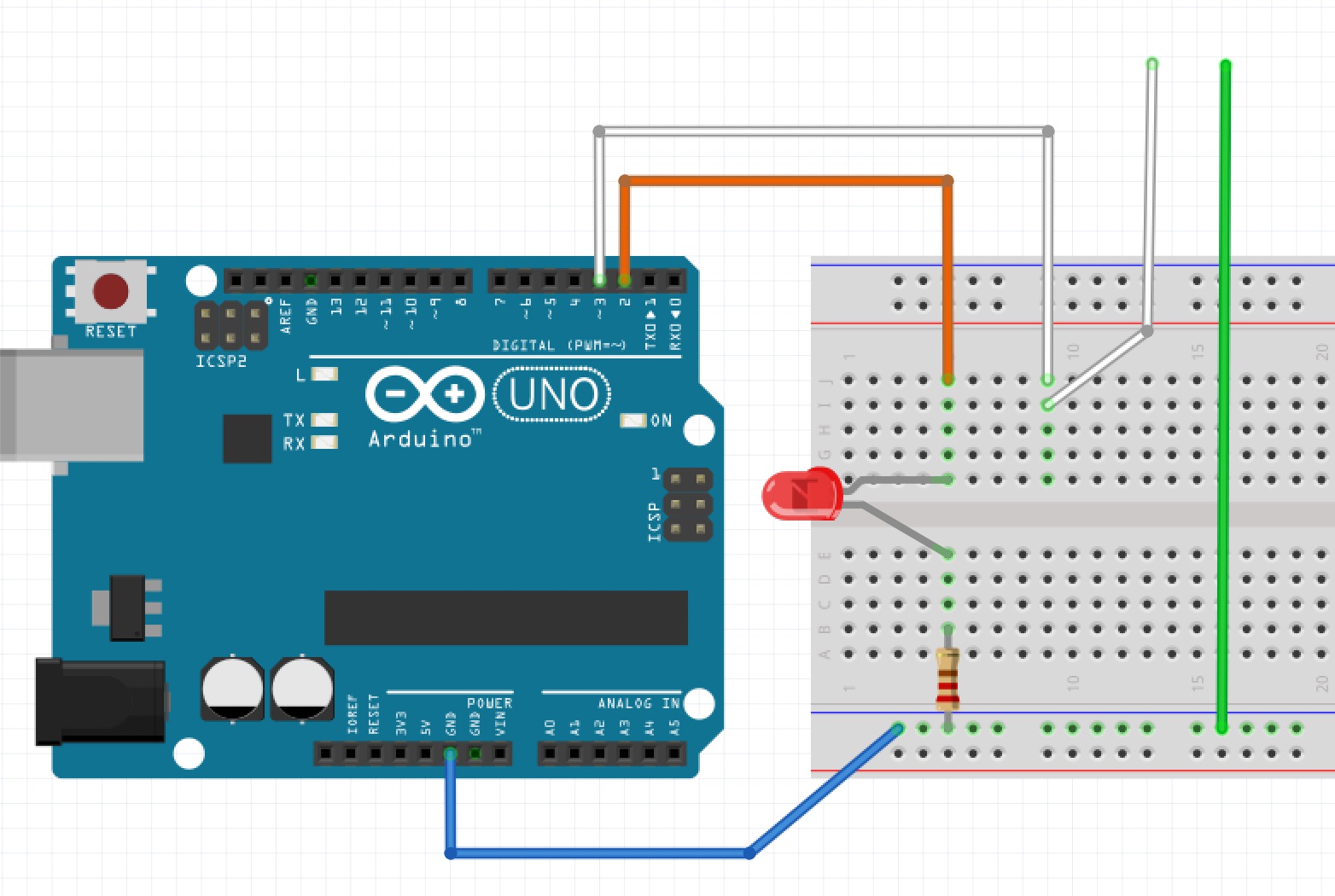
Continuity Tester
We will build and code a simple circuit to test continuity or conductivity of out circuit. It is just a circuit to be able to make a connection between a pin and ground through a circuit or part. If the circuit is complete or the part is a conductor the pin reading will go from HIGH to LOW we can use this value to control the LED.
We will build and code a simple circuit to test continuity or conductivity of out circuit. It is just a circuit to be able to make a connection between a pin and ground through a circuit or part. If the circuit is complete or the part is a conductor the pin reading will go from HIGH to LOW we can use this value to control the LED.
The code for this is using :
pinMode(3,INPUT_PULLUP);
digitalRead(3);
Further we can use the value read to control the LED using:
digitalWrite(2, digitalRead(3));
delay(10);
Since we are putting this in our loop we add the short delay of 10 msec to slow things down.
the NOT operator
It may be more intuitive for the light to be on when we have conductivity. The code and circuit above makes the light go off when we have conductivity. A boolean variable can be changed from true to false or false to true using the NOT operator. Consider this: NOT true = false and NOT false = true. The syntax for this is the exclamation point so !true = false, !false = true. Now the code looks like this:
void setup() {
  // put your setup code here, to run once:
Serial.begin(9600);
pinMode(2,OUTPUT);
pinMode(3, INPUT_PULLUP);
digitalWrite(2,HIGH);
delay(500);
digitalWrite(2,LOW);
delay(500);
digitalWrite(2,HIGH);
delay(500);
digitalWrite(2,LOW);
delay(500);
digitalWrite(2,HIGH);
delay(500);
}

void loop() {
  // put your main code here, to run repeatedly:
Serial.println("Hello World");
digitalWrite(2, !digitalRead(3));
delay(10);
}
Try it:
Analog Input
If we need to measure a voltage that is continuous like it could be 1 volt or 5 volts or anything in between this is called Analog. The arduino UNO has some input pins that can take an analog input. We will use:
analogRead(A1);
We will directly print it out by using it in a print statement like this:
void setup() {
  // put your setup code here, to run once:
  Serial.begin(9600);
  pinMode(2, OUTPUT);
  pinMode(3, INPUT_PULLUP);
  digitalWrite(2, HIGH);
  delay(500);
  digitalWrite(2, LOW);
  delay(500);
  digitalWrite(2, HIGH);
  delay(500);
  digitalWrite(2, LOW);
  delay(500);
  digitalWrite(2, HIGH);
  delay(500);
}

void loop() {
  // put your main code here, to run repeatedly:
  Serial.print("Hello World   ");
  digitalWrite(2, !digitalRead(3));
  Serial.println(analogRead(A1));
  delay(30);
}
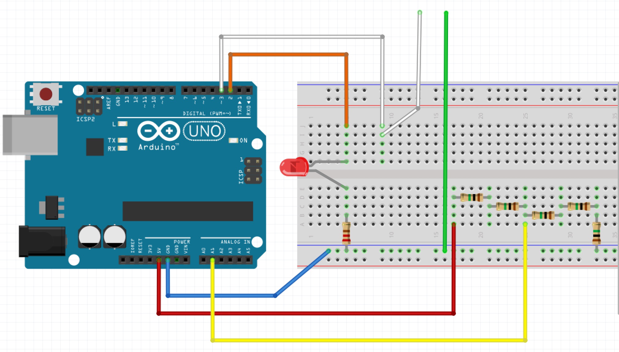
Here is the breadboard voltage divider circuit similar to the previous lesson but now connected to the arduino analog input. Move the yellow wire up and down the divider connections and observe the values printed to the screen.
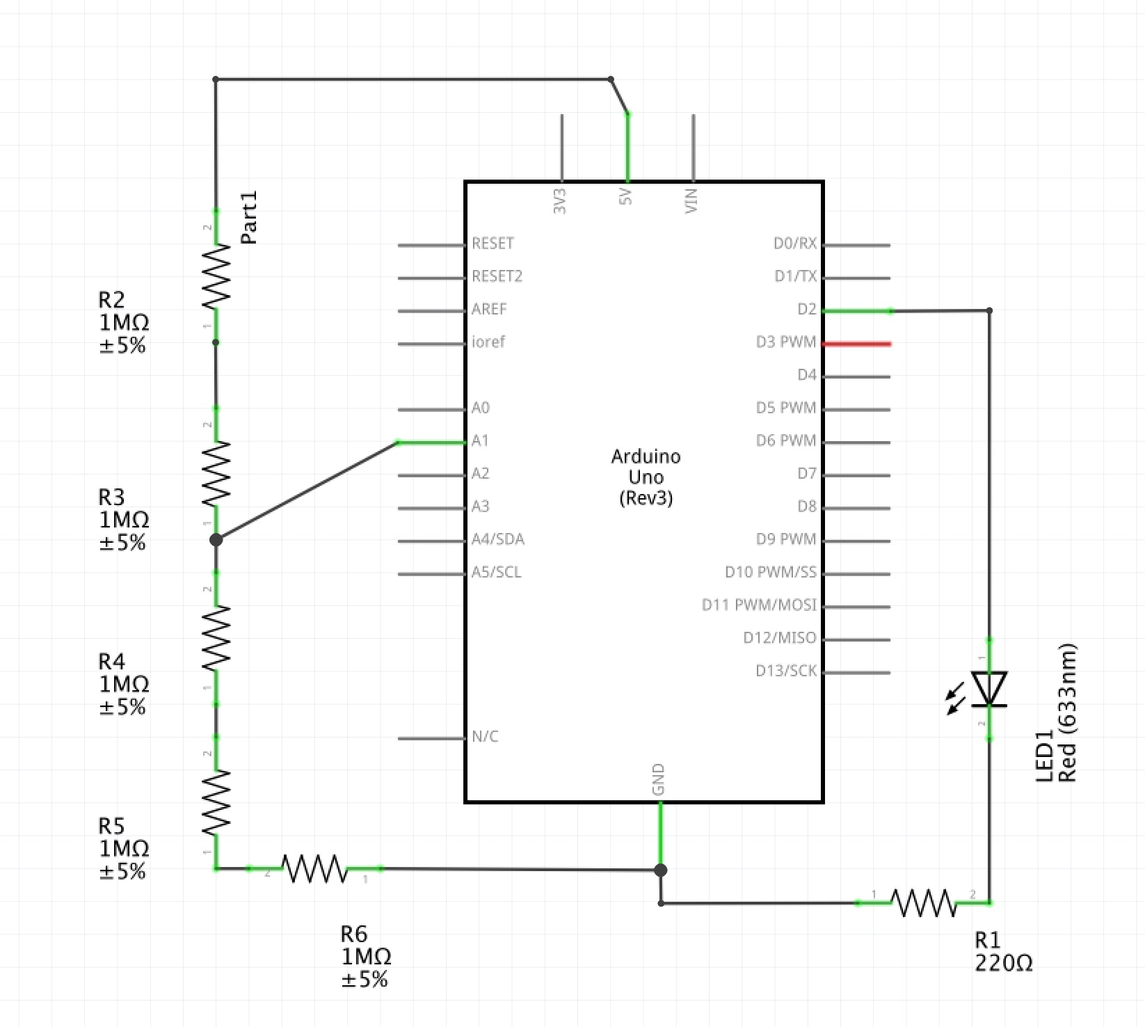
This is the full schematic for this lesson
Calibration
The Arduino UNO analog read results in a value from 0 to 1023 . 1023 corresponds to 5 Volts. So to read the actual voltage we need to do some math. multiply the read by 5 / 1023.
5.0*analogRead(A1)/1023;
We need to be careful to use floating point numbers rather than integers. If we used integers we could only measure to the nearest volt.
So edit our code to read:
Serial.println(5.0*analogRead(A1)/1023);