Electronic Circuits
In this lesson we will learn and build some simple circuits using a power source, conductors, resistors, LED lights and switches. We will also learn how to make simple electronics schematic diagrams.
Breadboard
the solderless breadboard is a component used to assemble prototype circuits. The same technology is used by students as well as design engineers. The breadboard has holes called tie points where wires can be inserted. The horizontal rows are connected. Vertical columns are not connected. Some breadboard have a power rail on one or both sides that is connected vertically, it is used for distributing power to your circuit.
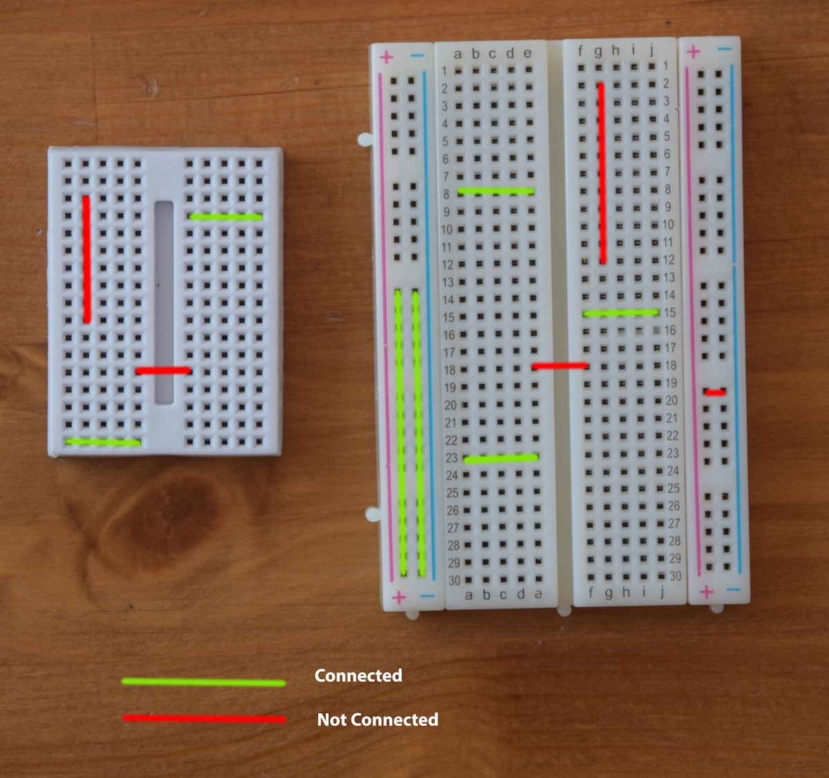
Connections on a breadboard. The green shows holes that are electrically connected while the red lines show where holes are not connected.
Power Source
Our circuits will require a power source this will usually be a battery but could also be power from a USB or a device. The important thing to know is that all power sources must have plus and minus sides or plus and ground. Many times we will use the power out from a microcontroller. The plus in that case will be labeled 5V or 3.3V or Vin and the minus is GND. On an Arduino UNO the Vin is the same as what ever battery or source that we power the Arduino. the 5V is regulated to be a constant 5V regardless of the power input source, similarly the 3.3V is regulated to 3.3V. GND is zero voltage.
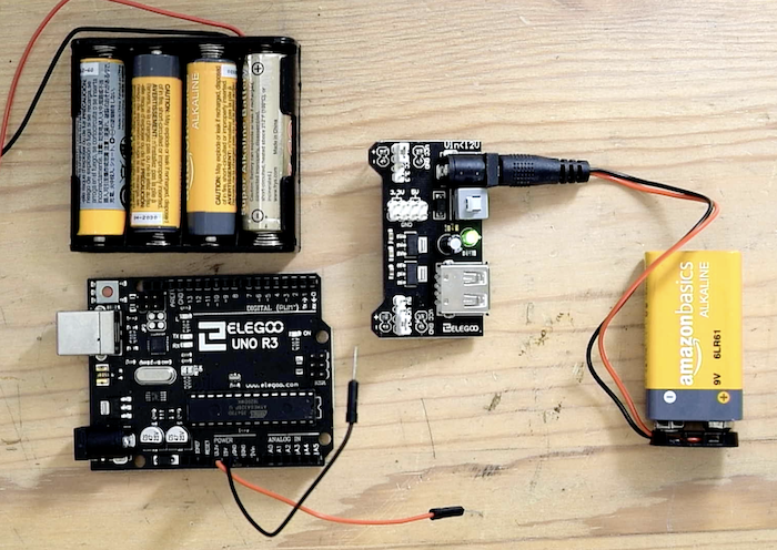
Different power sources we may use. Batteries, power output from Arduino, and and electronics power supply.
Conductors and Insulators
Also known as wires. We will use them to make connections between our devices using the breadboard. On a schematic diagram they are indicated by solid lines.
LED Lights
LED stands for Light Emitting Diode. What is a diode, you ask? A diode is a device that allows for electricity to flow one way but not the other. We'll get to why that's important a little later. The LED light is a simple, efficient light source that is showing up everywhere. LEDs not only make our world brighter, they are also the way that many electronic devices and robots ?talk? to us. Some example are:
- Your computer's "on" light. That light is an LED!
- Find your favorite toy. If it blinks, the thing blinking is an LED!
- Many cars have headlights that turn on during the day. Many of these are LEDs because of their long lifespans and efficiency.
Breadboard
The breadboard is a tool used for prototyping electronic circuits. Some of our students have said it should be called a waffle board, looks more like a waffle than a piece of bread. It is a simple way to connect up circuits. When you put a wire in one of the holes it connects it to many others as indicated by the yellow dots. In the middle of the board the horizontal rows of dots connect. On the sides there are 2 vertical columns of holes that connect, these are usually used for connecting our power source (battery).The breadboard has a right and left half that are not connected across the middle gap.
LED Light
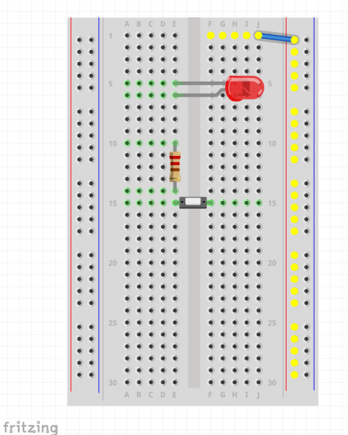
Connected at Row 5 is a red LED light. Remember when we said a diode is a device that allows electricity to flow one way but not the other? Well, this is why an LED needs to connected properly. If not, then the electricity can flow in the wrong direction, creating a break in the circuit. And when that happens, the light can't turn on. This is why it is important to know how your LED is connected. Usually the + wire is the longer one.
Resistor
The resistor is a device that "resists" the flow of electricity. It serves to protect our LED from too much current flowing through it. Too much current could damage it. Our resistor here is connected to row 10 on one end and row 14 at the other.
Push Button Switch
A push button switch is connected at Row 15. The switch crosses the middle gap connecting the two sides of the breadboard. A switch works like a door for electricity. When we switch it on the electrical charges can flow through it, when it is off they can not go through. One strange thing about the language of electronics is that when the switch is "closed" the electrical charges can go through and when it is open they cannot.
LED Circuit
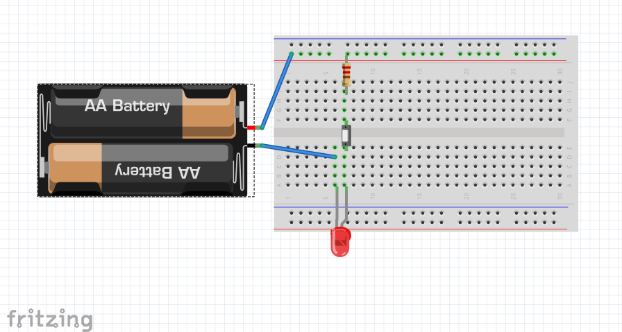
Here is a circuit using the LED, Switch and Resistor powered by a couple of batteries. Your instructor will help you make the connections, remember attention to detail maters, be sure to connect things in the right rows. The blue lines are wires, they can be any color and routed in anyway, the important thing is where the ends connect.
Project
Experiment with circuits using more LEDs, switches or different values of resistors etc.
Invention Project
Create a Conductor Tester
In our LED circuit the switch was what determined if the light was on or not. The switch completed the circuit when pushed. Suppose we remove the switch and replace it with two jumper wires If we touch the wires together the LED will light. We can use the jumpers to touch a sample material that we want to determine if it is a conductor or insulator. If the LED light up it is a conductor.
Try it yourself.