Schematic Diagrams
Schematic diagrams are the language of electrical engineering. We need to learn a few symbols and how they connect. With this new language we can more easily communicate our electronic invention ideas to others.
The schematics shown here were developed with a software called fritzing. You can also just sketch these by hand. Download Fritzing Here
This diagram shows the circuit of the previous lesson
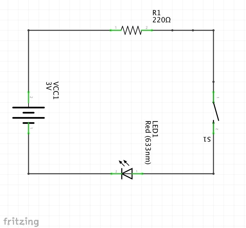
This is the schematic representation of the same circuit. We use special symbols to represent the components, you should learn these few. VCC1 is the Battery, R1 is the Resistor, S1 is the switch, LED1 is the LED light. Note that these may be labeled with some number values. The battery is 3V or 3 volts, the Resistor is 220 ohms, ohms is a measure of resistance the more ohms the less current that will flow from our 3 V battery through the circuit. The LED is labeled (633 nm) this is how we describe the color red, it is the wavelength of the light, more on this when we use different colors.
Complete Circuit There are two types of electrical charges + or positive and - or negative. In the normal world + and - charges stay together and the charges are balanced. In a battery there is a chemical reaction that separates the + and - charges . Given the chance the + charges and - charges want to get back together. We can make our LED to turn on if we create a path for the charges to move through our device and get back together. This movement of charge is called current. This circuit is only complete when the switch S1 is pushed to the closed position allowing the charges to move through it.