Potentiometer and Joystick
A variable Resistor
the potentiometer is a device that can give us a variable resistance value. In more detail it has 3 connections and actually gives two variable resistance values.

This is the symbol for a potentiometer. It looks like a resistor but with a third connection that is the arrow. In schematics an arrow generally indicates a variable circuit component. In the potentiometer the connection with the arrow is the one that moves and provides a variable resistance value.
A Sliding Connection
using the symbol above you can visualize how the potentiometer works. imagine that you can slide the arrow connection to the right or left so it connects to different points on the resistor symbol. As you move to the right the amount of resistor on the left gets bigger and the amount of resistor on the right gets smaller. The total resistance has some set value, in our case it is 10,000 ohms. and we split this between the left and right sides so we could have something like. 1,000 - 9,000. or 5,000 - 5,000 or 9,000 - 1,000 or even 10,000 - 0. The potentiometer gives us a continuous range of values so it is an Analog Device.
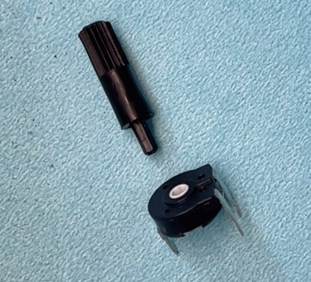
This is the physical potentiometer component that comes in the elegoo kit. The potentiometer is the 3 leg part, there is also an optional knob shown here to make adjusting the potentiometer easy. If you do know have the black knob for turning you can use a small screw driver with hex head. size 5/64
Circuit Wiring
We will use the potentiometer as a voltage divider circuit. You can review the Voltage Divider at our previous lesson. In our circuit the two resistors of the potentiometer will share or divide the voltage. This way as we adjust the potentiometer we will get a variable voltage on the moving connection. We will be able to adjust from 0 to the full 5V.
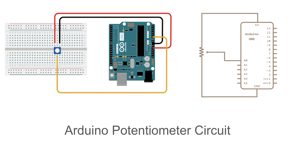
Here is the picture and the schematic digram of the circuit.
Arduino Code
We will start with Arduino code that reads the value of the voltage and prints it to the computer screen. Later we will extend it to a voltage level indicator using 3 LED lights.
The potentiometer circuit provides a continuously variable voltage so it is an Analog component. We will use
analogRead()
to read the value of the voltage. We will read the value into the variable sensorValue and then print it to the serial monitor.
int sensorPin = A0;

void setup() {
  //set up things pin selections and variables
  Serial.begin(9600); // opens serial port, sets data rate to 9600 bps
}

void loop() {
  // put your main code here, to run repeatedly:
  int sensorValue = analogRead(sensorPin);
  Serial.println(sensorValue);
  delay(50);
}
Upload and run the code to your arduino board. Open a serial monitor and adjust the potentiometer.
An extension of this code is to add an LED light and use the sensorValue to adjust the blinking rate of the LED. To start we will use the built in LED on the Arduino Uno board. The LED is at pin 13. The LED is either on or off so it is a Digital output device. We will use
digitalWrite()
to control the LED and a delay that will be adjusted by the potentiometer. The
delay()
takes a value in msec and waits for that amount of time. The
analogRead()
gives a value between 0 and 1023, so using this in delay will give that many msec of wait time.
Here is the code:
int sensorPin = A0;

void setup() {
  //set up things pin selections and variables
  Serial.begin(9600); // opens serial port, sets data rate to 9600 bps
  pinMode(13,OUTPUT);
}

void loop() {
  // put your main code here, to run repeatedly:
  int sensorValue = analogRead(sensorPin);
  Serial.println(sensorValue);
  // turn the ledPin on
  digitalWrite(13, HIGH);
  // stop the program for  milliseconds:
  delay(sensorValue);
  // turn the ledPin off:
  digitalWrite(13, LOW);
  // stop the program for for  milliseconds:
  delay(sensorValue);
}
The Joystick
The Joystick is a clever arrangement of 2 potentiometers. This way we can get two variable resistance values one when we move the joystick up and down and another when we move it side to side.

Picture of the joystick. You can see the two potentiometers. if you move the stick you can see them move. Most Joystick also have a switch pushbutton. The pin connections are 5V, GND, axis1, axis2 and switch.
The Circuit
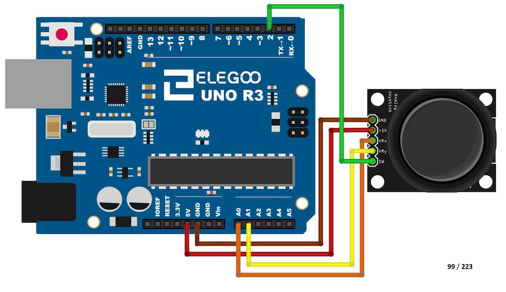
Here is the picture of wiring. The switch connection , green wire to pin 2 is optional.
The Arduino Code
Try to extend the previous code to read the two potentiometers of the joystick and print it to the screen. You will need to use
analogRead()
twice. And have two variables probably something like xValue and yValue. Try to print to the screen something like this:
xValue = 512
yValue = 128
The numbers will change as you move the joystick.