Joystick Light Controller
You Control the Lightshow
Here we will build a circuit and write code to make lights that are controlled by the joystick. You may want to review the Potentiometer lesson and the Circuits lesson before proceeding.
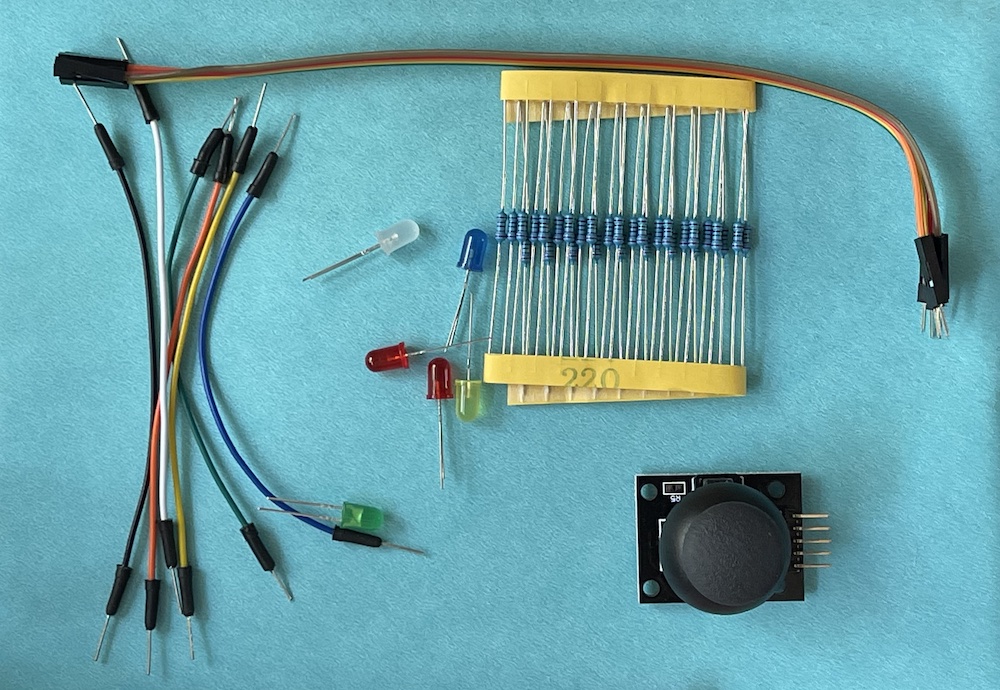
Parts for the LightShow Project
In addition to the Arduino Uno Board and your Breadboard you will need:
- 5 short jumper wires
- 5 LED lights
- 5 Resistors 220 ohm
- The Joystick
- 5 wire ribbon cable
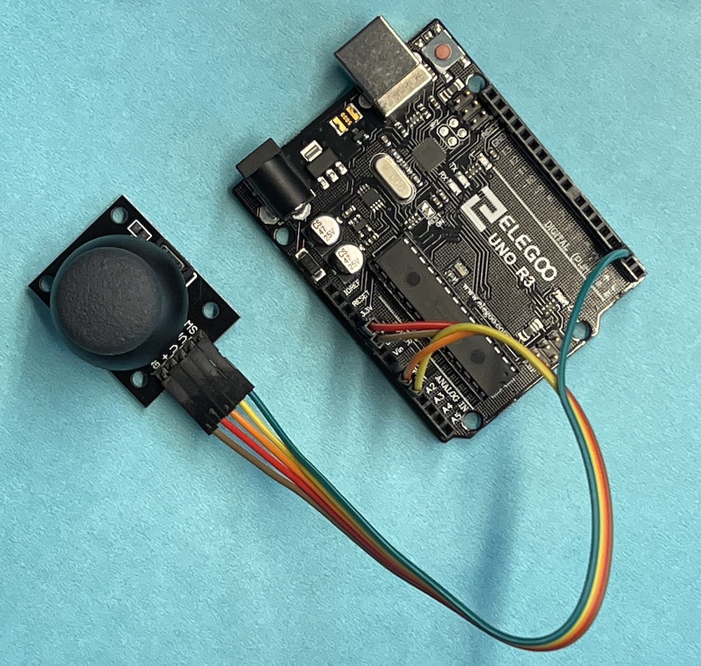
Photo of the wired Joystick and Arduino Board. See the Potentiometer lesson for details.
Code to Read the Joystick
with the joystick wired we can now write code to read the values of the two potentiometers. Since the values can change over a complete and continuous range we will use analog input to get the values. The Joystick also has a pushbutton switch that is either pressed or not, this would be a digital input.
const int xStick=A0; //global constants for pin connections
const int yStick=A1;

void setup() {
  // put your setup code here, to run once:
Serial.begin(9600);  //start a serial connection
}

//function to get the joystick value, returns and integer
int getJoystick(int stickPin)
{
  int val=analogRead(stickPin);
  return val;
}

void loop() {
  // put your main code here, to run repeatedly:
int x=getJoystick(xStick);
Serial.print("x = ");
Serial.println(x);
}
This code prints the value of the joystick to the serial monitor. It uses analogRead so it gives a value between 0 and 1023.
Try it Yourself
Add code to read and print the y value of the joystick. You will need another call to getJoystick and add some more print lines.
LED LightShow
We will now build a circuit to control 5 LED lights with the Joystick. First you will need to build up a circuit of five LEDs and Resistors on your breadboard. You should review the LED Circuit in the digital electronics lesson.
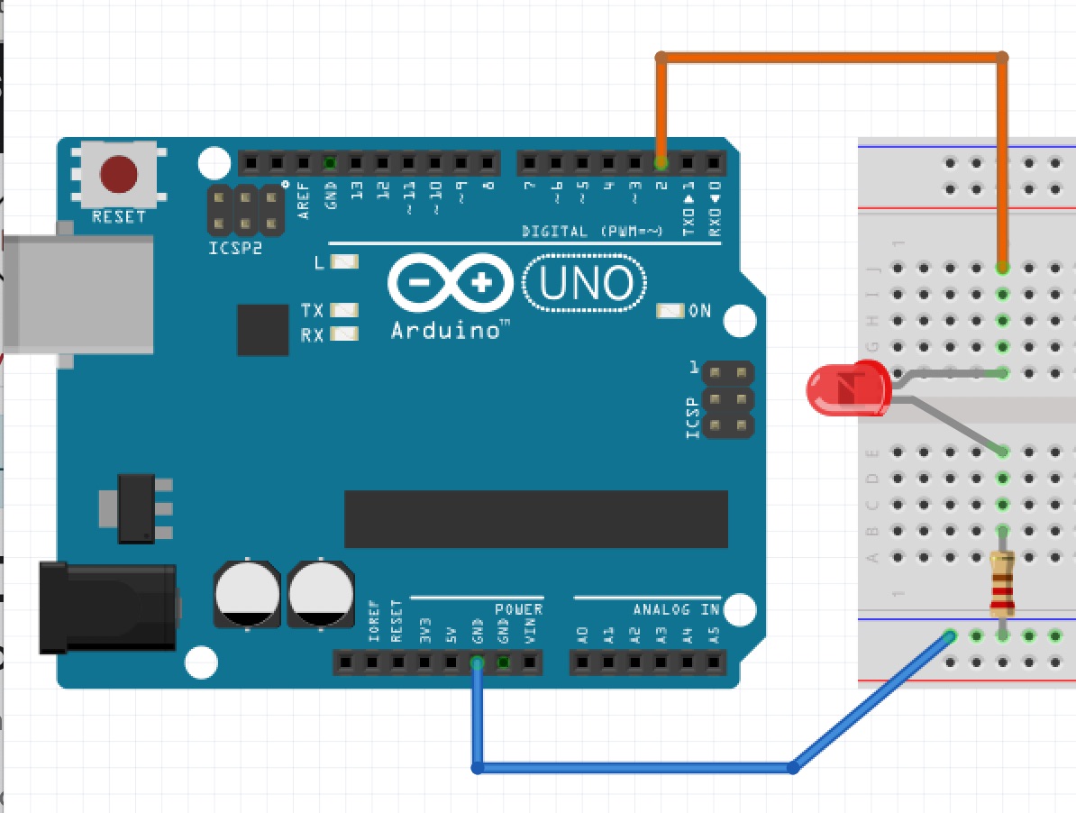
We are basically reproducing the LED circuit 5 times each connected to a different pin. Remember the LED has a plus and minus side, the plus is the longer wire and it should connect by jumper wire to the Arduino input pin. The minus side connects through the resisto to the blue line on the breadboard. This line is then connected through a jumper wire to the GND on Arduino.
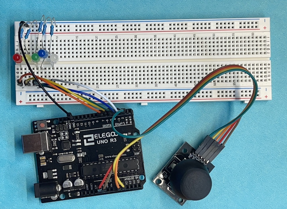
Here is the circuit with 5 LED. We basically duplicate the single LED circuit five times. We have connected the positive or plus side of the LED to pins 3,4,5,6 and 7. and the negative or minus through a 220 ohm resistor to GND . You can choose other pin connections but then your code will be slightly different than what is shown in this lesson.
Code to test the LED Circuit
Add this code to your previous sketch or start a new one.
const int white=3;
const int blue=4;
const int green=5;
const int yellow=6;
const int red=7;

void testLED()
{
  //Turn them all on to test
digitalWrite(white,1);
delay(500);
digitalWrite(blue,1);
delay(500);
digitalWrite(green,1);
delay(500);
digitalWrite(yellow,1);
delay(500);
digitalWrite(red,1);
delay(500);
//Then turn them off
digitalWrite(red,0);
delay(500);
digitalWrite(yellow,0);
delay(500);
digitalWrite(green,0);
delay(500);
digitalWrite(blue,0);
delay(500);
digitalWrite(white,0);
delay(500);

}
void setup() {
  // put your setup code here, to run once:
Serial.begin(9600);  //start a serial connection
//Set LED s as output
pinMode(white,OUTPUT);
pinMode(blue,OUTPUT);
pinMode(green,OUTPUT);
pinMode(yellow,OUTPUT);
pinMode(red,OUTPUT);

testLED();
}

void loop() {
  // put your main code here, to run repeatedly:
}
First we set up global constants to tell what pins the LEDs are connected to. This makes it easier to change things and easier for humans to read.
The Arduino digital pins can be OUTPUT or INPUT so in setUp we need to tell the Arduino that we will be using the pins as output. We use pinMode(pin, OUTPUT) to set them.
Next as a test we will turn on each LED. The LEDs are either on or off so they are a digital output and we use digitalWrite to control them, 1 means on and 0 means off. We delay a short time between each light. We have written this code in the function testLED(), Upload this to the Arduino and see if your lights all turn one. You can push reset on the Arduino UNO to run it again. If one of the lights does not light check the connection and the orientation of plus and minus. Fix thing to get all the lights working before proceeding.
Function to Control All 5 LEDs
We now write a function to control the state of all 5 LEDs. This contains all the code so that we can just make a single line function call with 5 arguments that will set the LEDs.
In the first example we just turn them all on or all off with the calls:
  lightLEDs(1,1,1,1,1);
  delay(500);
  lightLEDs(0,0,0,0,0);
  delay(500);
but we could also call with any configuration such as:
lightLEDs(1, 0, 0, 0, 0);
  delay(500);
  lightLEDs(1, 1, 0, 0, 0);
  delay(500);
  lightLEDs(1, 1, 1, 0, 0);
  delay(500);
  lightLEDs(1, 1, 1, 1, 0);
  delay(500);
  lightLEDs(1, 1, 1, 1, 1);
  delay(500);
  lightLEDs(0, 0, 0, 0, 0);
  delay(500);
Joystick Control
here is a function to control the LEDs based on an input value:
void lightShow(int val)
{
  if (val<150) lightLEDs(0,0,0,0,0);
  else if (val<300) lightLEDs(1,0,0,0,0);
  else if (val<450) lightLEDs(1,1,0,0,0);
  else if (val<600) lightLEDs(1,1,1,0,0);
  else if (val<750) lightLEDs(1,1,1,1,0);
  else  lightLEDs(1,1,1,1,1);
}
Example Code
Here is a working example:
const int xStick = A0; //global constants for pin connections
const int yStick = A1;
const int white = 3;
const int blue = 4;
const int green = 5;
const int yellow = 6;
const int red = 7;

void testLED()
{
  //Turn them all on to test
  digitalWrite(white, 1);
  delay(500);
  digitalWrite(blue, 1);
  delay(500);
  digitalWrite(green, 1);
  delay(500);
  digitalWrite(yellow, 1);
  delay(500);
  digitalWrite(red, 1);
  delay(500);
  //Then turn them off
  digitalWrite(red, 0);
  delay(500);
  digitalWrite(yellow, 0);
  delay(500);
  digitalWrite(green, 0);
  delay(500);
  digitalWrite(blue, 0);
  delay(500);
  digitalWrite(white, 0);
  delay(500);

}

void lightLEDs(bool redState, bool yellowState, bool greenState, bool blueState, bool whiteState)
{
  digitalWrite(red, redState);
  digitalWrite(yellow, yellowState);
  digitalWrite(green, greenState);
  digitalWrite(blue, blueState);
  digitalWrite(white, whiteState);
}

//function to get the joystick value, returns and integer
int getJoystick(int stickPin)
{
  int val = analogRead(stickPin);
  return val;
}

void lightShow(int val)
{
  if (val < 150) lightLEDs(0, 0, 0, 0, 0);
  else if (val < 300) lightLEDs(1, 0, 0, 0, 0);
  else if (val < 450) lightLEDs(0, 1, 0, 0, 0);
  else if (val < 600) lightLEDs(0, 0, 1, 0, 0);
  else if (val < 750) lightLEDs(0, 0, 0, 1, 0);
  else  lightLEDs(0, 0, 0, 0, 1);
}

void setup() {
  // put your setup code here, to run once:
  Serial.begin(9600);  //start a serial connection
  //Set LED s as output
  pinMode(white, OUTPUT);
  pinMode(blue, OUTPUT);
  pinMode(green, OUTPUT);
  pinMode(yellow, OUTPUT);
  pinMode(red, OUTPUT);

  testLED();
}

void loop() {
  // put your main code here, to run repeatedly:
  int x = getJoystick(xStick);
  Serial.print("x = ");
  Serial.println(x);
  lightShow(x);
  delay(10);
}