Stepper Motor
Controlling a Motor by Steps
The Stepper is a motor that we can move in discrete steps. This way we can move to a very specific position. these motors are what makes devices like 3D printers and Laser Cutters possible. A 3 D printer would use 3 of these motors to allow us to move to any point in 3D space, A laser cutter is a 2D device so there are two of these motors that move the laser mirror to any position on a 2D plane.
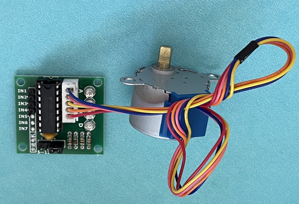
This is the stepper motor and its driver board. It needs the board to control it. Our connections to the board are 5V and GND and 4 digital pins for control.
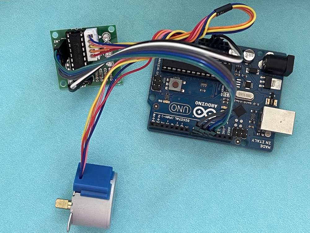
The motor driver board can be connected to Arduino with a single ribbon cable. The power connection is labeled - + 5 - 12V. Connect the - to GND and the + to 5V. There is a set of 4 pins labeled IN4- 1. connect these to digital pins on the arduino. To use our example code the connections should be IN4 to 8, IN3 to 9 , IN2 to 10 and IN1 to 11. if you connect to other pins you will have to modify the code.
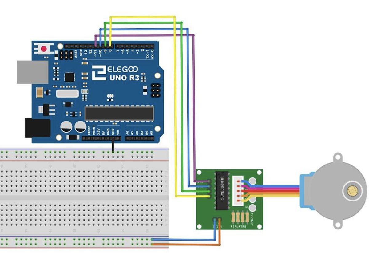
This is the wiring of the stepper motor and controller. here is a google drive link to the complete Tutorial from Elegoo.
Example Code to Move Stepper
this code uses the library stepper.h
//www.elegoo.com
//2018.10.25

/*
  Stepper Motor Control - one revolution

  This program drives a unipolar or bipolar stepper motor.
  The motor is attached to digital pins 8 - 11 of the Arduino.

  The motor should revolve one revolution in one direction, then
  one revolution in the other direction.

*/

#include <Stepper.h>

const int stepsPerRevolution = 2048;  // change this to fit the number of steps per revolution
const int rolePerMinute = 15;         // Adjustable range of 28BYJ-48 stepper is 0~17 rpm

// initialize the stepper library on pins 8 through 11:
Stepper myStepper(stepsPerRevolution, 8, 10, 9, 11);

void setup() {
  myStepper.setSpeed(rolePerMinute);
  // initialize the serial port:
  Serial.begin(9600);
}

void loop() {
  // step one revolution in one direction:
  Serial.println("clockwise");
  myStepper.step(stepsPerRevolution);
  delay(500);

  // step one revolution in the other direction:
  Serial.println("counterclockwise");
  myStepper.step(-stepsPerRevolution);
  delay(500);
}
This code will rotate the stepper one complete turn clockwise, then one complete turn counterclockwise. You can change the rolePerMinute value to make it slower or a little faster. You can replace the stepsPerRevolution in the myStepper.step(stepsPerRevolution); call to some number like 500 to make only a partial revolution. Play with the code to see what happens.
Joystick to Move Stepper Motor
Set up the Joystick as in the Joystick lesson
if you follow this you will see that the joystick wants to be connected to 5V and the stepper also needs a connection to 5V. We would need to use a breadboard or some other multi-wire connection to make this happen.
What is Vin and 5V ?
Vin is the input voltage from the USB or the battery, 5V is a regulated 5V output there is a circuit on the Arduino board that takes the Vin and makes a regulated 5V output. On the Stepper controller we have similar regulator so we do not have to provide 5V we can just connect to Vin. When using the USB connection the Vin is still 5V, it is only different if we use a barrety input, in that case it could be 9V or whatever the battery voltage is.
So connect the + of the stepper controller board to Vin and the Joystick to 5V
Joystick Control Example Code
Now with the joystick connected we get the x position of the joystick by an analogRead of pin A1
analogRead(A1) will return a number between 0 and 1023, 0 means the stick is full left, 1023 means full right. Lets write code that moves clockwise if A1 is >600 and counterclockwise if A1 is <400.
void loop() {
  int x=analogRead(A1);
  Serial.println(x);
  if(x>600)
  {
  // step one revolution in one direction:
  Serial.println("clockwise");
  myStepper.step(10);
  delay(10);
  }
if(x<400)
{
  // step one revolution in the other direction:
  Serial.println("counterclockwise");
  myStepper.step(-10);
  delay(10);\
}
}
Stepper with 4982 Driver
Stepper and driver circuit from a 3D printer. We can controll it also with our arduino microcontroller.
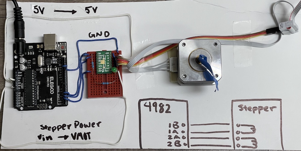
Wiring for the Big Stepper with the 4982 driver and arduino UNO.
Stepper with 4982 Driver
Arduino code for moving the stepper with the 4982 controller
#define EN    2
#define STEP  3
#define DIR   4

bool dir = false;

void setup() {
  // put your setup code here, to run once:
  pinMode(EN, OUTPUT);
  pinMode(STEP, OUTPUT);
  pinMode(DIR, OUTPUT);

  digitalWrite(EN, LOW); // enable the stepper motor
  digitalWrite(DIR, dir); // set direction to CCW
}

void loop() {
  for (int i = 0; i < 3600; i++) {
    digitalWrite(STEP, HIGH);
    delayMicroseconds(10); // to ensure driver reads pulse

    digitalWrite(STEP, LOW);
    delayMicroseconds(350); // delay before next step
  }
  dir = !dir; // change spin direction
  digitalWrite(DIR, dir); // set direction
//  delay(800);
}